
Power Electronics Engineering Design Services
 Inductor and Transformer Design
Electronic Ballast: Flourescent Lamp and LED
Automotive Power Supplies: Engine and Body Modules
Single Phase Power Factor Correction Solutions
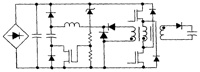
A POWER FACTOR CORRECTED, MOSFET, MULTIPLE OUTPUT, FLYBACK SWITCHING SUPPLY (PDF) This paper discusses the subject of power factor correction and its importance in the field of power conversion. Present industry techniques are discussed, and by combining portions of these methods, a new circuit is created that provides power factor correction at 90% or greater. A multiple-output blocking oscillator and a P.W.M. were built to prove the theory with test results given. |
Electronic Fluorescent Ballast using a Power Factor Correction Techniques for Loads Greater than 300 Watts (PDF) This paper describes various power factor schemes used to correct power factor in electronic ballast or other types of power supplies. The power inverter used for the fluorescent lamp load is a Current Fed Sine Wave Inverter while the unique power factor correction and dimming is accomplished with a boost approach. Keeping the inverter the same, several historical passive techniques were designed, built, and tested; these results are to be used as a bench mark against the active power factor circuit topologies. The results are given for a matrix of low, normal and high line voltages of a 4 lamp load greater than 300 watts. |
Power Factor Correction Techniques Used For Flourescent Lamp Ballast (PDF) IEEE Industry Applications Society Conference, October, 1991. Design Goal: |
Power Factor Motorola Solutions (PDF) APEC Boston, 1992 - Review of Math |